Overview
Image Processing can be applied to a variety of workflow steps to enhance image quality and readability for OCR and other data extraction processes. The Image Processing feature tunes a variety of available image enhancement processes to your unique needs, and then performs them during the given workflow step.
NOTE: Using similar options provided with a scanner may process slightly faster as they occur at the hardware level and should be tried first.
Image Processing in Multiple Product Areas
Image Processing can be accessed in multiple areas of Configuration. In some instances, Options and Trigger tabs will be enabled based on the product area. However, the Available Commands section should remain universal throughout these product areas.
Image Processing in the Capture Profile Root
The Image Processing Profiles dialog box has various profiles listed. A new profile can be added, or an existing profile edited. NOTE: All settings should be defined previously by the system administrator. However, some scan operators may wish to make adjustments to the settings to suit the needs of a particular batch or page.
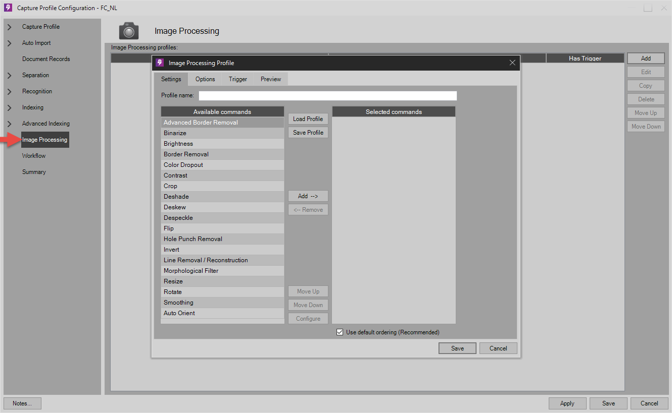
When accessing Image Processing from the Capture Profile Configuration root, four tabs are presented:
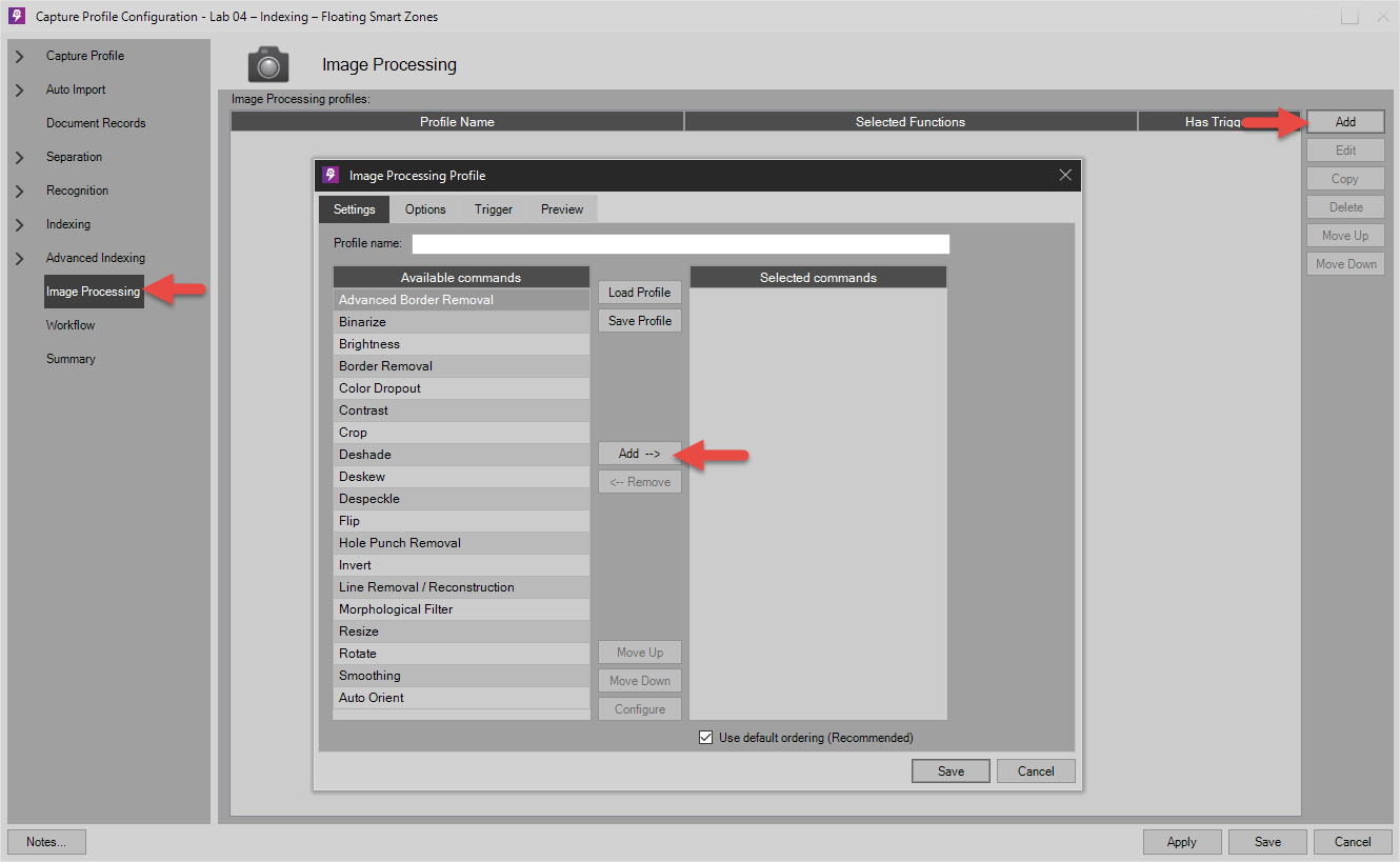
Image Processing Profiles
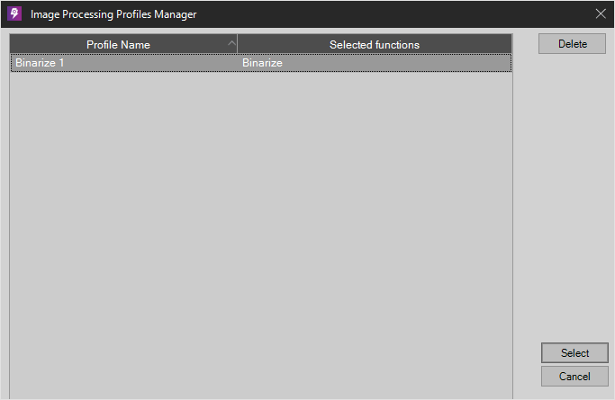
On the toolbar of the right of the main areas, Administrators can Add, Edit, Copy, Delete, or Move Up / Down their Image Processing Profiles as it suits their business needs. When loading an image processing profile for use in a QA Auto Processing Workflow Step, or a Migration pre-processing step, a load screen similar to the one below will appear, where Administrators can select from their list of Image Processing Profiles premade in this area:
Profile Name
Enter a unique but easily identifiable name for the profile being configured. Numerous profiles can exist for varying conditions.
Image Processing Settings
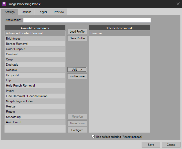
NOTE: In some Migration workflow step pre-processing tabs and other PSIcapture product areas, the Options and Trigger tabs may not be available. Use the Capture Profile Root section identified above in instances where these tabs are necessary for your workflow.
Add -->
Click to Add a new profile or Edit to make changes to an existing profile.
<-- Remove
Copy the selected Image Processing Profile.
Move Up
Move the selected profile up in the list
Move Down
Move the selected profile down in the list
Configure
Configure the selected Image Processing Profiles in detail.
The user may select any of the appropriate image processing functions by adding them to the right side. It is highly recommended that the “Use default ordering” be checked.
Use default ordering (Recommended)
While the user is able to move each command up and down, it is recommended that each command be processed in the default ordering to aid speed and accuracy.
Image Enhancement Commands
Advanced Border Removal
Automatically removes black/white borders from an image using a sophisticated object detection algorithm.
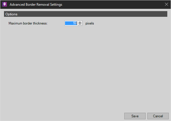
Maximum/Minimum Border Thickness
Set in pixels the amount of thickness range. Any blank space above the maximum will be removed, below the minimum will remain.
Binarize
Converts a grayscale or color image to black and white using the selected Binarize method.

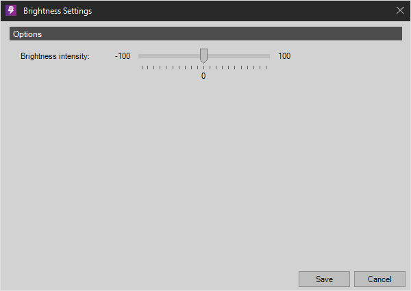
Brightness
Modifies the Brightness of a grayscale or color image. Move the slider toward the positive side to yield brighter images.
Border Removal
Removes solid borders from images. (do not use if using Advance Border Removal)
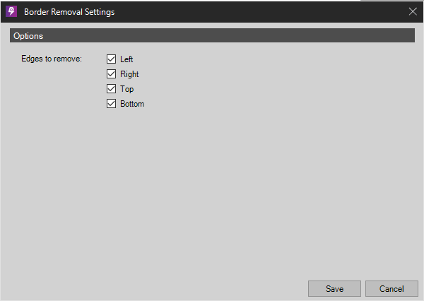
Edges to Remove
Choose to perform border removal on individual or all sides of the image.
Color Dropout
Enables the user to discard specific color(s) from color images. Example: useful when scanning scantron forms.
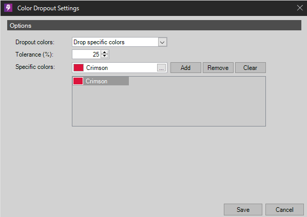
Dropout Colors
Choose “Drop Specific Colors” to specify color(s). Choose “Drop All Colors” will essentially binarize the image.
Specific Colors
User can select various colors to add to the list via a dropdown list containing some common colors or sample custom colors by clicking ICON.
Color Matching
Choose between Hue/Value, Hue/Saturation and Saturation/Value.
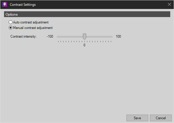
Contrast
Either automatically using the built in algorithm or manually using the slide bar provided to modify the Contrast of a grayscale or color image. Move the slider toward positive side to increase the difference between light and dark regions of an image.
Crop
Allows an image to be either manually cropped or automatically cropped.
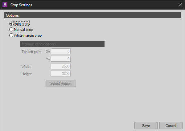
Auto Crop
Threshold allows a value to be set via the slider to adjust the amount of blank region on a page being removed.
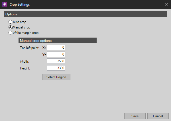
Manual Crop
Allows users to set a region on an image to be cropped. Fields “X” and “Y” denotes the coordinates at the top left corner in pixels. “Width” and “Height” denotes the size in pixels of the resulting image. NOTE: The “X” and “Y” coordinates will change depending on the resolution (DPI) of the image being captured. Do not use this option if capturing images with varying resolutions.
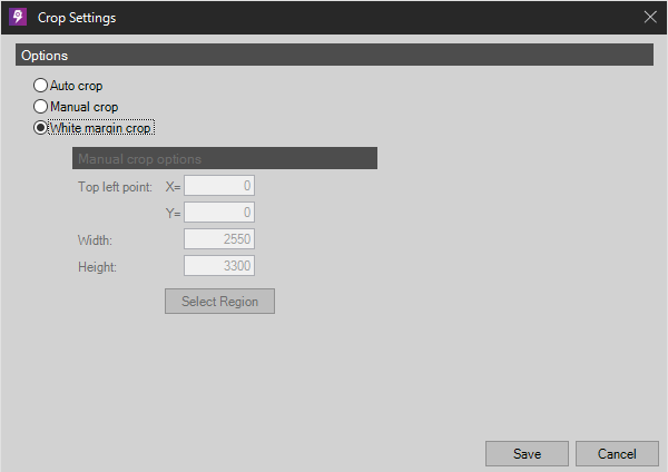
White Margin Crop
Will crop an image by removing solid color borders around the edge of an image.
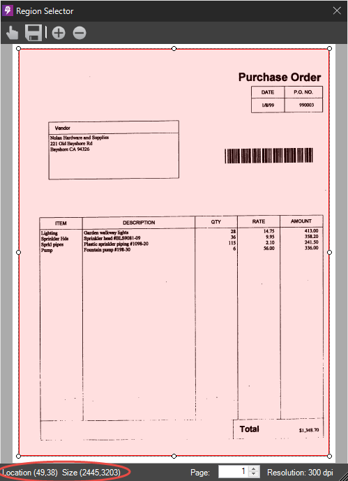
Select Region - Use the mouse by point to the top left of the region desired then click and hold the left mouse button, drag to the opposite corner of the desired region and then let go of the left mouse button. A red outlined region will appear as below. The location and size of the zone will appear at the bottom of “Region Selector”.
![]() - Select Template Image to load a sample image. NOTE: this image must have the same resolution as the image that will be captured later in order for the region location and size to be accurate.
- Select Template Image to load a sample image. NOTE: this image must have the same resolution as the image that will be captured later in order for the region location and size to be accurate.
![]() - Save Region populates location and size values in the corresponding fields in the “Crop Settings” window.
- Save Region populates location and size values in the corresponding fields in the “Crop Settings” window.
![]() - Zoom in
- Zoom in
![]() - Zoom Out
- Zoom Out
Deshade
Reduces small black regions within the image.
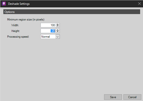
Minimum Region Size
Set width and height for the smallest region allowed.
Processing Speed
Select between Normal, Fast (default), Faster, or Fastest based on emphasis of speed versus accuracy.
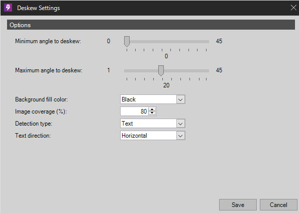
De-skew
Automatically straightens an image.
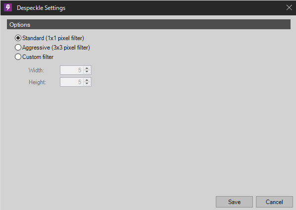
Despeckle
This command cleans the image of small speckles by using either a Standard (1 x 1 pixel), Aggressive (3 x 3) or custom filter.
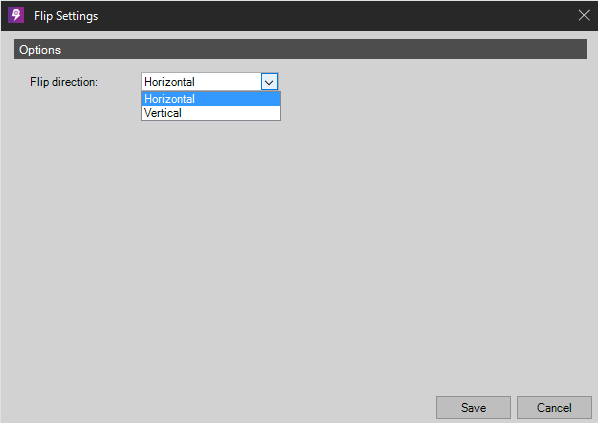
Flip
Flips an image either horizontally or vertically.
Hole Punch Removal
This is used when scanning/importing pages that had been hole punched thus leaving small black circles near the edges. This command will fill in those black dots with white.
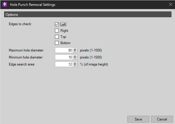
- Edges to Check - Select one or multiple edges to process.
- Maximum/Minimum Hole Diameter - Displayed in pixels, black marks larger than the maximum diameter and smaller than the minimum diameter will not be affected.
- Edge Search Area - Search this percentage of the image height and width to determine the region where holes may be.
Invert
This command is used to convert images with white text and black background to black text and white background, or vice versa.
Line Removal / Reconstruction
This command is used to remove lines and may be especially helpful during zone OCR.
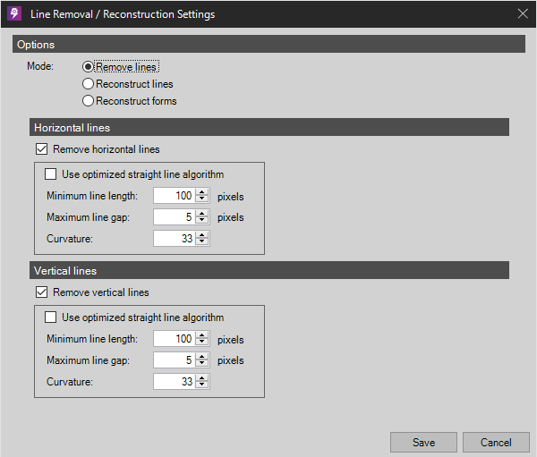
Options
Mode - Choose from one of the following:
- Remove lines - Remove detected lines with the parameters below.
- Reconstruct lines - Reconstruct detected lines with the parameters below.
- Reconstruct forms - Reconstruct the forms of boxes with the parameters below.
Horizontal Lines
Remove horizontal lines - Select to remove horizontal lines when detected.
Use optimized straight line algorithm - The straight line algorithm will attempt to determine a consistent occurrence of spacing between lines and optimize accordingly.
Minimum Line Length - Set in pixels the minimum length that should determine a line. This will prevent characters such as “1” or “/” to be removed unintentionally.
Maximum Line Gap - Set in pixels the amount of space between the lines. Only lines appearing farther than this setting will be removed.
Curvature - Some lines within your document may have curves. Set the maximum degree of the curvature to be detected.
Vertical lines
Remove vertical lines - Select to remove horizontal lines when detected.
Use optimized straight line algorithm - The straight line algorithm will attempt to determine a consistent occurrence of spacing between lines and optimize accordingly.
Minimum Line Length - Set in pixels the minimum length that should determine a line. This will prevent characters such as “1” or “/” to be removed unintentionally.
Maximum Line Gap - Set in pixels the amount of space between the lines. Only lines appearing farther than this setting will be removed.
Curvature - Some lines within your document may have curves. Set the maximum degree of the curvature to be detected.
Morphological Filters
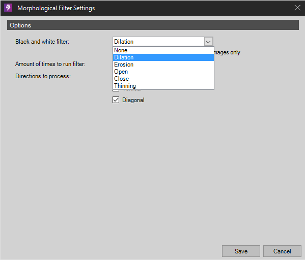
Processes captured images with one of the following filters:
- Dilation - Used to smooth small dark regions tending to enhance black features in the image. (Darken)
- Erosion - Used to smooth small light regions tending to reduce black features in the image. (Lighten)
- Open - The dilation of the erosion of the image used to reduce small black regions within the image. (Deshade)
- Close - The erosion of the dilation of the image used to reduce small white regions within the image. (Light Thicken)
- Boundary Extraction (B/W only) - Perform a boundary detection/extraction on a binary image. This will generate an outline of the foreground features of the input image.
- Thinning (B/W only) - Reduces the geometric size of an image, leaving only a skeletonized frame in its place.
Resize
Allows image to be resized to a set of user defined dimensions.
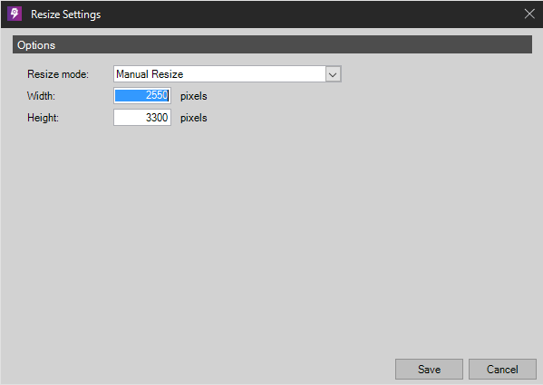
Resize Mode
Allows Manual Resize, Maintain Aspect Ratio Using Width, or Maintain Aspect Ratio Using Height
New Size
Enter new width and height dimensions in pixels.
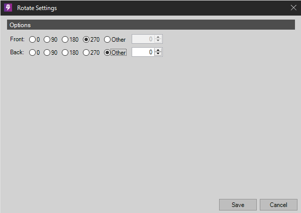
Rotate
Automatically rotates an image clockwise by 90-degree increments or by the user specified number of degrees. The front and back (if existing) can be configured independently.
Options
NOTE: This tab is only available under the main Configuration Page of your Capture Profile:
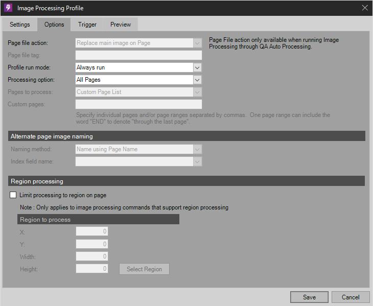
Profile Options
Page File Action
Replace main page image is the only option.
Page File Tag
This option is unavailable.
Profile Run Mode
Choose Always run, Only run when triggered, or Disabled
Pages to Process
Choose which page or pages to process. NOTE: Separate multiple pages with commas. Leaving this option blank will cause ALL pages to have this process run on them.
Alternate Page Image Naming
NOTE: Alternate Image support is only available when running Image Processing in QA Auto Processing.
Naming Method
Choose to the alternate image using Page Name, Trigger Value, or Index Field.
Index Field Name
Specify index field name when choosing index field as a naming method.
Region Processing
Limit processing to region on page
Check to limit processing to a specific region, otherwise processing will be done to the entire page.
NOTE: Only applies to image processing commands that support region processing - It's important to note that attempting to limit a region on an image processing command that is meant to apply to an entire page, such as Binarize, can yield undesired results.
Region to Process
Allows users to set a region on an image to be cropped. Fields “X” and “Y” denotes the coordinates at the top left corner in pixels. “Width” and “Height” denotes the size in pixels of the resulting image. NOTE: The “X” and “Y” coordinates will change depending on the resolution (DPI) of the image being captured. Do not use this option if capturing images with varying resolutions.
Select Region
Use the mouse by point to the top left of the region desired then click and hold the left mouse button, drag to the opposite corner of the desired region and then let go of the left mouse button. A red outlined region will appear as below. The location and size of the zone will appear at the bottom of “Region Selector”.
![]() - Select Template Image to load a sample image. NOTE: this image must have the same resolution as the image that will be captured later in order for the region location and size to be accurate.
- Select Template Image to load a sample image. NOTE: this image must have the same resolution as the image that will be captured later in order for the region location and size to be accurate.
![]() - Save Region populates location and size values in the corresponding fields in the “Crop Settings” window.
- Save Region populates location and size values in the corresponding fields in the “Crop Settings” window.
![]() - Zoom in
- Zoom in
![]() - Zoom Out
- Zoom Out
Trigger
NOTE: Triggers only run in the Quality Assurance module.
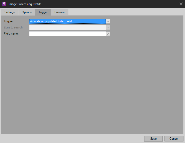
Profile Trigger
Trigger
- No Image Processing Trigger – The trigger is disabled.
- Activate on Any Barcode – Any barcode read will cause activation of this profile.
- Activate on specific Barcode values and patterns – Regular expressions can be used to create a desired pattern. If a barcode is read and matches the pattern activation of this profile will occur.
- Activate on any Patch Code – Any patch code will cause activation of this profile.
- Activate on a specific Patch Code – Choose from patch code types I, II, III, IV, VI, or T to activate this profile.
- Activate on a populated Index Field – Choose a field from the Field Name drop down box and if this field contains data at the time Image Processing is run, it will cause activation of this profile.
- Activate on specific Index Field values and patterns – Choose a field from the Field Name drop down box and if this field contains data that matches the values and/or patterns at the time Image Processing is run, it will cause activation of this profile.
Zone to search
This option is unavailable.
Field Name
Specify an index field containing the value(s) in the triggering event.
Values to Activate On
Value(s) added are stored here for viewing and/or editing with Edit, Remove, or Clear All.
Add Multiple
Allows users to add multiple activate patterns at once. Each line is considered a new pattern.
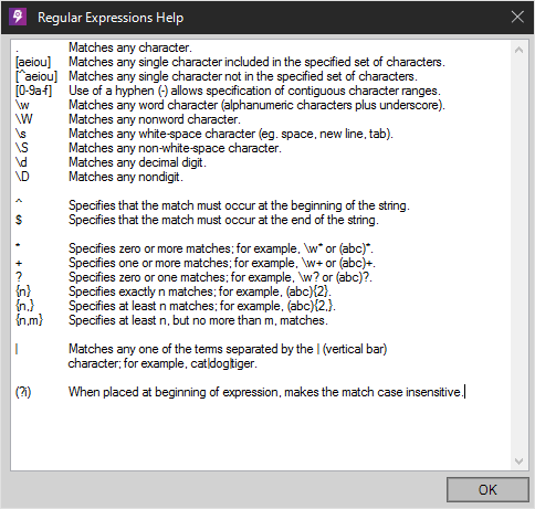
Help
View regular expressions symbols for pattern matching.
Match Case
Enabling this option makes all the Values to Activate case sensitive.
Example Expression:
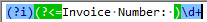 (?i)(?<=Invoice Number: )\d+
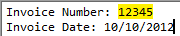 Invoice Number: 12345
Invoice Date: 10/10/2012
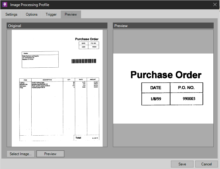
Preview
Load an original image (shown on the left) via “Select Image”. Click “Preview” to apply image processing commands as defined in Settings. The result will be shown on the right. Above figure is an example of manual cropping.
Keywords: PSIcapture Image Processing, Image Processing PSIcapture, How to Image Process in PSIcapture
Comments
Article is closed for comments.